EFRATOM LPRO-101 Pin 7 voltage vs. offset in PPB
This document describes the relation ship between the voltage on PIN 7 and the deviation in part per billion (ppb)
On the diagram below you can see the applied voltage on the X-axis and the offset in ppb on the Y-axis
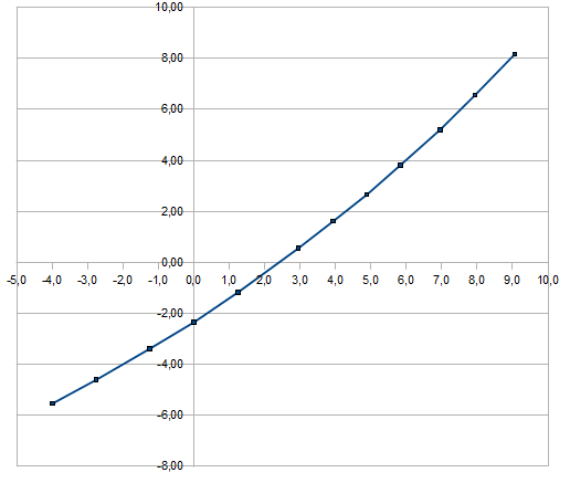
The following formula calculates the offset as function of the voltage:
f(x) = -2.2426 + 0.927099 * x + 0.026193 * x^2
Using the UNIX “dc” command to calculate for example for x=0 :
export X=0 ; dc <<< "20k _2.2426 0.927099 $X * + 0.026193 $X d ** + p"
-2.242600
The inverse function describes the voltage as function of the offset:
f(y) = 2.242 + 0.989116 * y - 0.0216413 * y^2
export Y=0 ; dc <<< "20k 2.242 0.989116 $Y * + _0.0216413 $Y d ** + p"
2.2420000
Hint: for negative numbers one has to use the underscore. It’s “dc” behavior.
export Y=_4 ; dc <<< "20k 2.242 0.989116 $Y * + _0.0216413 $Y d ** + p"
-2.0607248
I made 2 measurements
This one is made with the trimmer in position counter clockwise
| voltage | ppb | |
|---|---|---|
| -3,985 | -5,53 | |
| -2,750 | -4,60 | |
| -1,250 | -3,39 | |
| 0,000 | -2,35 | |
| 1,255 | -1,17 | |
| 2,945 | 0,55 | |
| 3,940 | 1,62 | |
| 4,890 | 2,66 | |
| 5,830 | 3,81 | |
| 6,960 | 5,21 | |
| 7,940 | 6,56 | |
| 9,060 | 8,16 |
Here the timer is turned clockwise
| voltage | ppb | |
|---|---|---|
| -3,960 | -5,52 | |
| -2,984 | -4,76 | |
| -1,253 | -3,36 | |
| 0,000 | -2,23 | |
| 1,253 | -1,04 | |
| 3,125 | 0,90 | |
| 3,920 | 1,77 | |
| 5,020 | 3,08 | |
| 5,960 | 4,21 | |
| 7,140 | 5,74 | |
| 8,050 | 6,91 | |
| 8,930 | 8,12 |
Actually there are no differences except some measuring inaccuracy.
Of course this is only true for my EFRATOM. Yours has maybe a different trajectory.